MSG® INTEGRALLY GEARED CENTRIFUGAL COMPRESSORS
MSG (multi-stage geared) compressors offer outstanding design flexibility. MSG compressors are application engineered with numerous available configurations:
- Flows from 4,200 to 230,000 m3/h (2500 to 135,000 CFM)
- Input capacity to over 18,650 kW (25,000 hp)
- Discharge pressures to 100 barg (1450 psig)
FEATURES
Oil-Free Air and Gas
- Prevents system contamination
- Reduces the potential for compressed air pipeline fires caused by oil carryover
- No costly waste disposal associated with oil-laden condensate
- Eliminates the expense and maintenance of oil separation filters at the discharge
High Reliability
MSG centrifugal compressors are designed to be extremely reliable due to:
- Conservative high-quality gear design
- Long-life pinion bearing design
- Thrust loads absorbed at low speed
- Stainless steel compression elements
Low Compressor Operating Life Cycle Cost
MSG centrifugal compressors provide better overall operating efficiency than positive displacement or other centrifugal compressors.
- Excellent efficiencies at full load, part load and no load
- Low maintenance cost
- Increased uptime from high-reliability design (limits the need for multiple unit installations for basic reliability reasons)
- No sliding or rubbing parts in the compression process that can cause wear and thereby efficiency loss
Easy Operation/Maintenance
1. State-of-the-art MAESTRO control systems
2. Fully automated operation for any process conditions
3. Machine self-diagnostics
4. Compression elements do not wear or require periodic replacement
5. Accessible horizontally split gearbox for quick inspection
6. Removable intercooler and aftercooler bundles for easy cleaning
Simple Installation
1. Compressor, lubrication system, intercoolers, shaft coupling, coupling guard, interconnecting piping, etc. on a common base
2. Easy installation with no special foundation requirements
3. Easy component accessibility
4. Site connection point flexibility
5. Reduced floor space required
6. Dynamic compression process is pulsation-free, so installation of additional dampening equipment is not required.
MSG centrifugal compressors are exceptional by design.
1. One, two or three rotors, up to six stages per gearbox
2. Horizontal splitline(s) for easy access to parts
APPLICATIONS
Engineered Air Applications
- Air Separation
- Industrial gases
- Instrument air
- Oil & Gas and Petrochemical Processes
- Soot blowers
- Large plant air
- Power Generation
Gas Compressor Applications
- Fuel gas boosting
- Renewable Natural Gas
- LNG
- Hydrogen Generation
- Natural gas gathering
- Hydrocarbon refrigeration gas
- Carbon monoxide
- CO2 (wet or dry)
- SynGas
- Low molecular weight recycle gas
- High-pressure nitrogen
- Landfill gas
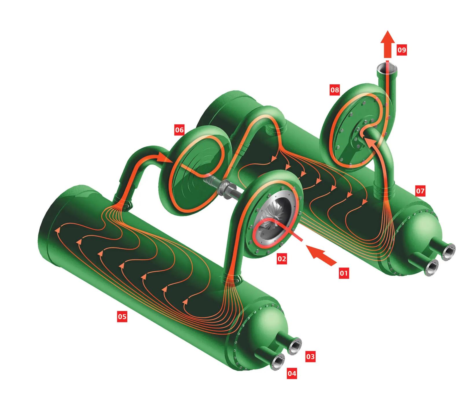
GAS FLOW ARRANGEMENT
MSG centrifugal compressors feature an advanced arrangement of gas flow components. Advantages of this arrangement include:
- Directed gas movement to reduce turbulence induced friction
- Air is cooled after every stage to provide high isothermal efficiency
Air Flow Diagram
- Compressor inlet
- First-stage compressor volute
- Coolant in
- Coolant out
- First-stage intercooler
- Second-stage compressor volute
- Second-stage intercooler
- Third-stage compressor volute
- Compressor discharge